MARINESHELF publishes articles contributed by seafarers and other marine related sites solely for the benefit of seafarers .All copyright materials are owned by its respective authors or publishers.
Axial


Rotodynamic
Pumps.
Basically defined by the flow pattern;
- Axial where the outlet flow is
parallel to the drive
- Radial where the outlet flow is at right angles to the drive Mixed – a bit of both
Axial

The pumping pressure is formed by the
propeller lift of the vanes.
They develop a very low head (max ~ 20m), but
have a very large mass flow rate
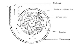
Radial
The most common form of centrifugal
pump.
Water enters the eye of the impeller
and is thrown out by centrifugal force. As water leaves the eye of the impeller
a low pressure area is created causing more liquid to flow toward the inlet
because of atmospheric pressure and centrifugal force. Velocity is developed as
the liquid flows through the impeller while it is turning at high speeds on the
shaft. The liquid velocity is collected
by the diffuser or volute and
converted to pressure by specially designed passageways that direct the flow to
discharge into the piping system; or, on to another impeller stage for further
increasing of pressure.
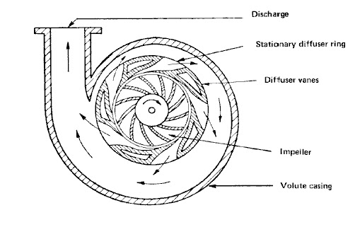

To make the conversion from velocity
to pressure more effective, stationary diffuser vanes can be installed around
the rim of the impeller. This construction gives rise to the term diffuser
centrifugal pump.
The head or pressure that a pump will
develop is in direct relation to the impeller diameter, the number of impellers,
the eye or inlet opening size, and how much velocity is developed from the
speed of the shaft rotation.
Capacity is determined by the exit
width of the impeller.
All of these factors affect the size
of the motor to be used; the more water to be pumped or pressure to be
developed, the more energy is needed.
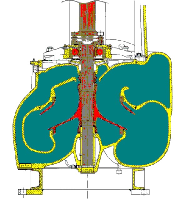
A double-entry impeller assures extremely low NPSH values.
The impeller has an inlet on either
side, lowering the friction resistance of the incoming fluid.
These pumps operate with about a 25%
reduction in NPSHR compared to a similar size end
suction centrifugal pump
These pumps are used for high capacity
applications, or any time you need a low net positive suction head required (NPSHR).
The double suction also prevents some
axial thrusting of the impeller
For higher pressures
the pumps can be arranged in multiple stages, the discharge from one stage
becomes the inlet to the next
Flow control can be arranged by using
multiple speed motors (variable speed is not common).
- Flow rate is directly
proportional to the rotation speed s
- Differential head is directly
proportional to the s2
- The power required is directly
proportional to (Flow x Head) i.e s3
 Mixed FlowA pump in which the head is developed partly by centrifugal force and partly by the lift of the vanes on the liquid.This type of pump has a single inlet impeller with the flow entering axially and discharging in an axial/radial direction

2 comments:
Hi,
You have really done the great job,wonderful article with informative stuff,i loves to follow your blog.
For complete details please visit centrifugal pumps
Thank you for your post, I look for such article along time, today i find it finally. If you're searching for Trusted and reputable Pump suppliers in India, then you can checkout here at @ TFTpumps.com, where we supply all kinds of Pumps to Industries.
Post a Comment